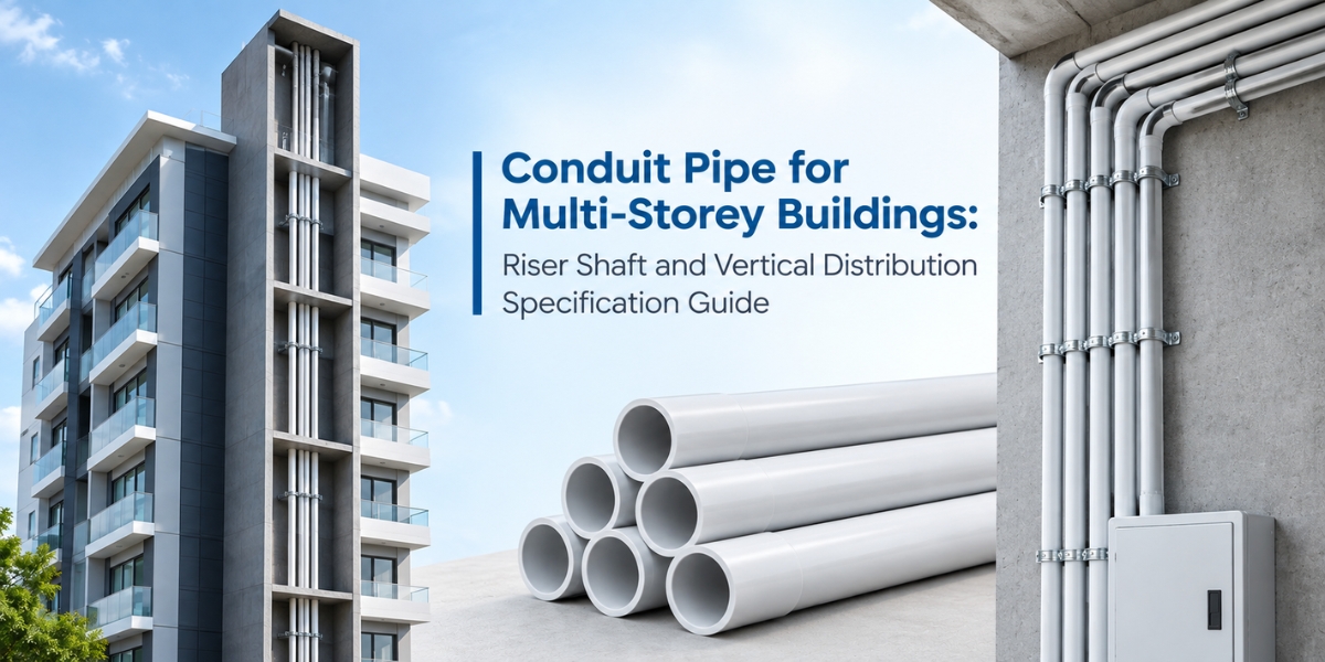
Every multi-storey building, residential or commercial, has one section of its electrical design that gets less attention than it deserves: the riser shaft. This is the vertical corridor that carries power from the main incoming supply on the ground floor up through every level of the building. Get the riser wrong and the consequences aren't cosmetic. A failed fire-stop at one floor penetration, an under-sized conduit that can't take a future load increase, or a joint that cracks from unaccounted-for thermal movement can affect every floor above the fault, not just one flat or one office.
This guide focuses specifically on the riser shaft and vertical distribution problem: what changes when conduit runs vertically through multiple floors instead of horizontally within one, and what a developer or MEP consultant needs to get right at the specification stage.
What makes a riser shaft different from a typical wiring run
A horizontal conduit run inside a single flat or office deals with one floor's structure, one set of loads, and a run length measured in metres. A riser shaft deals with a run length measured in tens of metres, passes through every intermediate floor slab along the way, and carries the combined load of every floor it serves, not just the load of one unit.
Three problems come with this that a typical residential wiring job never has to solve:
- Cumulative load. The conduit and cable at the bottom of a ten-storey riser carries the electrical load of all ten floors, while the conduit near the top carries only the load of the floors above it. Sizing has to account for this tapering load rather than using one size throughout.
- Multiple fire compartments. Every floor slab the riser passes through is typically a fire compartment boundary. A shaft that isn't properly sealed at each level turns into a chimney for fire and smoke to travel between floors, defeating the compartmentation the rest of the building's fire design depends on.
- Long-run thermal movement. A vertical run spanning several floors experiences far more cumulative thermal expansion and contraction than any single-floor horizontal run, and this needs to be designed for rather than discovered later as cracked joints.
Grade selection for vertical runs
Conduit grade in a riser shaft should be selected based on where in the vertical run a section sits, not applied uniformly top to bottom.
Lower sections carrying the full building load
The bottom sections of a riser, especially in a taller building, typically carry heavier cable bundles serving multiple floors' worth of demand. Heavy Mechanical Stress (HMS) grade conduit is generally the right choice here, both for the higher mechanical protection needed around denser cable bundles and because these sections are harder to access for repair once the building is occupied. Trity Pipes manufactures HMS grade conduit specifically for this kind of high-load, low-access application, with the wall thickness and impact resistance to hold up in the busiest section of a shaft for the life of the building.
Upper sections and branch-off points
As the riser ascends and cable bundles thin out with each floor's supply branching off, Medium Mechanical Stress (MMS) grade is often adequate for the remaining vertical run. This isn't a corner-cutting decision, since MMS is still a fully compliant grade for the loads it's carrying at that point in the run. It's a cost-efficient match between grade and actual mechanical demand at each section. Trity Pipes supplies both HMS and MMS grades from the same product range, manufactured to matching dimensional tolerances, so a project can transition grades partway up a riser without introducing a fitting mismatch at the changeover point.
Fire performance across the whole run
Regardless of where a section sits in the shaft, conduit throughout a riser should meet flame-retardant, low-smoke performance suited to a shaft that runs the full height of the building. This is a separate consideration from mechanical grade and shouldn't be assumed to come bundled with any particular LMS/MMS/HMS choice; confirm the specific product's fire rating with the manufacturer. Trity Pipes' conduit range is manufactured to self-extinguishing, low-smoke performance across all three grades, so a riser specification doesn't have to trade off fire performance against mechanical grade selection.
Fire-stopping at every floor slab penetration
This is the single most safety-critical detail in riser shaft design, and it's worth understanding the regulatory backdrop before getting into the practical side.
India's fire safety requirements for buildings have historically run through NBC 2016 Part 4, which set the baseline for high-rise classification, compartmentation, and life safety provisions most states currently reference in their building bye-laws. In May 2026, the Bureau of Indian Standards released NBCS 2026 Part F as a substantially expanded successor, with updated thresholds and new provisions for occupancy types like data centres and EV parking. It's important to note that NBCS 2026 is explicitly advisory rather than mandatory. It becomes enforceable only where a state government formally adopts it through local building bye-laws or a fire services act, so project teams should confirm which standard actually applies in their state rather than assuming either one automatically governs.
What doesn't change between the two frameworks is the underlying principle: a fire-rated floor slab is only as effective as its penetrations are sealed. A riser shaft passing conduit and cable through a two-hour fire-rated slab needs a tested through-penetration firestop system at every single floor crossing, not just at the ends of the run.
In practice, this means:
- Every point where conduit passes through a floor slab in the riser needs a fire-stop material or system rated to match the fire resistance of the slab it penetrates, not a generic sealant
- The annular gap between the conduit and the slab opening needs to be filled with a tested firestop compound, since an unsealed gap defeats the slab's fire rating regardless of how well-built the rest of the shaft is
- Firestopping needs to be inspected and signed off floor by floor during construction, since this is one of the details most likely to get missed or done inconsistently by different subcontractors working different floors
- Any later modification to the riser, such as adding a new cable run for a tenant fit-out, needs to reinstate the firestop properly at that penetration rather than leaving it open after the work is done
Consistent, ISI-certified wall thickness matters here too. Trity Pipes' conduit is manufactured to a controlled outer diameter tolerance, which keeps the annular gap at each slab penetration predictable for the firestop installer rather than varying batch to batch.
Given that NBCS 2026 has raised compartment size allowances in several categories and introduced new occupancy-specific fire compartmentation rules, a project team working on a large or mixed-use tower should confirm with their fire safety consultant which framework applies before finalising the riser's fire-stopping specification, particularly for any data centre, EV parking, or mixed-occupancy component in the building.
Expansion allowance over long vertical runs
uPVC has a meaningfully higher coefficient of thermal expansion than the concrete and steel structure it's fixed to, and this becomes a real design consideration once a conduit run spans multiple floors rather than a single room.
What happens without proper expansion allowance:
A rigidly fixed, unbroken vertical run of conduit expands and contracts as ambient temperature shifts through the day and across seasons. Over a run spanning several floors, this movement adds up. Without anywhere to go, that movement transfers stress onto the nearest fixed joint or bracket, and over years of repeated cycling this is a common, quiet cause of cracked solvent-welded joints inside a shaft that nobody notices until a fault develops.
How to design for it:
- Incorporate expansion couplers at intervals recommended by the manufacturer for the specific conduit size and expected temperature range in the shaft, allowing the pipe to move slightly within the fitting rather than transferring stress to a rigid joint
- Avoid fixing every bracket point rigidly along the full run; a mix of fixed and sliding support points lets the pipe expand and contract without binding
- Account for the fact that riser shafts in India can see meaningfully different internal temperatures depending on ventilation, proximity to the building's exterior wall, and whether the shaft is naturally ventilated or fully enclosed, all of which affect how much expansion allowance is actually needed
Trity Pipes supplies expansion couplers dimensionally matched to our full conduit size range, so this detail can be specified directly from our fittings catalogue rather than sourced separately and checked for fit on site.
Coordinating conduit with cable tray in the same shaft
In many multi-storey buildings, especially larger commercial towers, hospitals, and mixed-use developments, the riser shaft doesn't carry conduit alone. Bulk distribution cabling serving the building's common systems often runs on cable tray through the same vertical space, with conduit reserved for smaller branch circuits and final connections at each floor.
Getting this coordination right at the design stage avoids two common problems: conduit and tray routed without enough clearance between them, making future access difficult, and confusion at each floor about which system a given circuit should actually use. Our detailed comparison of conduit pipe and cable tray covers the broader decision logic between the two systems, which applies directly to planning how a riser shaft should split its vertical distribution between bulk tray runs and point-protection conduit.
As a general pattern for riser design, tray typically carries the shaft's bulk vertical distribution to floor-level distribution boards, while conduit takes over from each distribution board outward to the specific circuits on that floor. This keeps the shaft itself organised and makes it far easier to trace and maintain individual circuits later. Trity Pipes' technical team regularly works with MEP consultants at exactly this handoff point, helping confirm conduit sizing and grade for the branch-circuit side of a riser design that pairs with a separately specified tray system.
Sizing for the tapering load down the shaft
A riser doesn't need to be sized uniformly from the ground floor to the roof, and treating it that way either wastes money on unnecessary size lower down or, more dangerously, under-sizes the busiest section.
A practical approach:
- Calculate the cumulative cable load the riser needs to carry at the base, where it serves every floor above it, and size conduit and any tray sections accordingly for that busiest stretch
- Reduce conduit size in stages as branch circuits split off to serve individual floors, following the same size-reduction logic used in any tapered electrical distribution design
- Build in genuine spare capacity, not just the bare minimum for day-one load, since riser shafts are the hardest and most expensive part of a building to retrofit once occupied; adding capacity later usually means significant disruption to occupied floors below the point of work
- Coordinate riser sizing with the electrical load calculation for the whole building rather than sizing it in isolation, since undersizing here creates a bottleneck regardless of how well each individual floor's wiring is specified
Trity Pipes manufactures conduit across the full 20mm to 63mm size range needed to specify a tapered riser from a single supplier, which keeps every size on the project dimensionally consistent with the same fitting range rather than mixing pipe from different manufacturers at each size transition.
Frequently asked questions
What grade of conduit pipe should be used in a riser shaft?
There isn't one single grade for the whole shaft. HMS is generally the right choice for the lower sections carrying the heaviest, hardest-to-access cable bundles, while MMS is often adequate for upper sections once branch circuits have split off and the remaining load is lighter. Fire performance (flame-retardant, low-smoke) should be confirmed separately from mechanical grade, since the two aren't automatically bundled together.
How is fire-stopping actually done at a riser shaft floor penetration?
A tested through-penetration firestop system is installed in the annular gap between the conduit and the slab opening, rated to match the fire resistance of the slab it passes through. This isn't a generic sealant job; it needs a system tested to the relevant standard, installed and inspected floor by floor during construction, and reinstated correctly any time a new cable run is added later.
Does NBC 2016 or NBCS 2026 apply to my building's riser shaft design?
It depends on your state. NBC 2016 Part 4 has been the mandatory reference for most Indian states until now. NBCS 2026 Part F, released in May 2026, is explicitly advisory and only becomes enforceable where a state government formally adopts it through building bye-laws or a fire services act. Confirm with your fire safety consultant which framework your state currently applies before finalising compartmentation and fire-stopping specifications, particularly for high-rise, data centre, or mixed-occupancy buildings where the two codes diverge most.
Why does a riser shaft need expansion couplers if a normal wall conduit run doesn't?
A short horizontal run inside one room experiences relatively little cumulative thermal movement. A riser shaft spans multiple floors, so the total expansion and contraction over its full length is much greater. Without expansion couplers at intervals, that movement has nowhere to go and transfers stress onto the nearest rigid joint, which is a common, slow-developing cause of cracked joints inside shafts that aren't inspected often.
Can conduit and cable tray share the same riser shaft?
Yes, and it's common practice in larger commercial and mixed-use buildings. Tray typically handles the shaft's bulk vertical distribution up to each floor's distribution board, while conduit takes over from the distribution board out to individual circuits on that floor. The key design task is leaving enough clearance between the two systems for future access and making it clear at each floor which system a given circuit belongs to.
Should riser shaft conduit be sized for current load or future load?
Future load, within reason. Riser shafts are among the most disruptive and expensive parts of a building to retrofit once it's occupied, since adding capacity later usually means work on floors below the point of modification. Sizing with genuine spare capacity at the design stage costs relatively little compared to the cost of expanding a riser after the building is in use.
Getting riser shaft specification right from the start
A riser shaft is unforgiving of mistakes precisely because it's difficult and disruptive to fix once a building is built and occupied. Grade selection matched to load at each section, properly tested fire-stopping at every single floor penetration, genuine expansion allowance over the full vertical run, and clear coordination between conduit and cable tray where both are present in the same shaft are the specification decisions that determine whether a riser performs reliably for the building's full working life or becomes a recurring maintenance problem.
For general commercial building wiring beyond the riser shaft itself, our guide to conduit pipe for commercial buildings covers office, retail, and hospitality applications in more depth. Trity Pipes manufactures ISI-certified uPVC conduit pipes and fittings across LMS, MMS, and HMS grades, suited to both the demanding lower sections and the lighter branch sections of a riser shaft design. You can review our full uPVC conduit pipes and fittings range for the sizes and grades that fit your project.
Designing riser shaft wiring for a multi-storey project? Get technical specification support from our team before you finalise your electrical drawings, and we'll help you match grade, size, and fitting selection to your building's actual vertical load profile.